Monday, 30 December 2013

Update..

Here's my current position using the BaroneOSD sample code here: http://www.elenafrancesco.org/old/arduino/baroneosd/

For some reason, it doesn't display on just one line. No idea why, could it be a PAL/NTSC conflict? Or something else? hmmm...


Sunday, 29 December 2013

Texas Instruments Sync Chip Samples

Here are my sample VSync chips. I think the LMH1980 or the LMH1981 are 3.3v which will make them out-of-the-box-suitable for my project.
The LMH1980 is so small I can't pick it up securely in my fingers, so I don't know how I am going to use it in my breadboard prototypes.... Very daunting. 

Name: 2013-12-29 15-25-31.337.jpg
Views: 11
Size: 72.8 KB
Description:

Wednesday, 25 December 2013

Samples Update

Just got a confirmation from T.i. Theyre sending me £30 worth of samples   

Saturday, 21 December 2013

samples

Just attempted to order a whole bunch of samples from Texas Instruments. They gave me a big f.u. last time. But fingers crossed again. It's really exciting because I found some really cool sync chips.

Progresssss

ooooh under 2g 

It looks good, but I'm a little sceptical about the ability to run on 3.7v as claimed, if only because it's running the MAX7456 which doesn't run on anything under 4.75v as says here: http://datasheets.maximintegrated.com/en/ds/MAX7456.pdf

I nearly got the barone osd circuit going last night. Still some flickering & some guesswork, but almost worked using the demo script. I think the BaroneOSD is the way to go for truly lightweight, 3.7v, and to make yourself at home (diy).

It looks like more & more people are looking into micro-quad osd's which is great news.

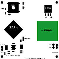
Doodled this circuit just earlier. Should be accurate, and as tiny an osd as there will ever be:
Name: benbojanglesosd_schema_1.jpg
Views: 14
Size: 82.2 KB
Description:

Tuesday, 17 December 2013

update

There's also this that is interesting me: 
Name: 123.JPG
Views: 5
Size: 28.3 KB
Description:

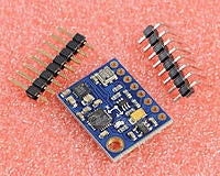
£12 from here

- 10DOF modules (three-axis gyroscope + triaxial accelerometer and three-axis magnetic field + atmospheric pressure) 
- Chip: MPU6050 + HMC5883L + BMP180 
- Power supply :3-5v 
- Means of communication: IIC communication protocol (fully compatible with 3-5v system containing LLC circuit) 
- Size: 2.2cm * 1.7cm

It would mean the possibility of having an artificial horizon 

Name: 1122.jpg
Views: 10
Size: 43.9 KB
Description:


Using the 5v booster idea, there's also this (more costly) possibilty of SimpleOSD:

Name: OSD-diag2.jpg
Views: 12
Size: 150.0 KB
Description:

SimpleOSD = £25 (plus import tax & postage) (£40)
Booster = £1
BMP180 = £2
= £43

More costly, but 4g in weight (as opposed to 8g & £13 of the Minimosd)

Sunday, 15 December 2013

benbojanglesosd update

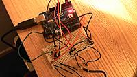
So, here is my progress in my benbojanglesosd experiment.

Name: 2013-12-15 17-22-33.651.jpg
Views: 8
Size: 54.7 KB
Description:

Name: 2013-12-15 17-22-53.522.jpg
Views: 7
Size: 290.5 KB
Description:

I'm finding it quite demanding, but I'm making advances. For someone who has never made an electronic circuit before, I'm not doing too badly 

Anyway, I have learned now, that there are stages/sections to this circuit.
-The Arduino: prints screen text
-LM1881 part: syncs/strips vsync data (somehow. I'm not fully understanding of it yet)
-Camera: displays screen video

I am not sure yet if the LM1881 is supposed to V-sync arduino data, camera picture, or both????? 
I learned, that if I just connect the arduino signal + camera video using a composite splitter adapter into the monitor, the picture is very very flickery.

So I guess that the LM1881 removes either one or both signal's vsync to allow both to merge. But I still don't get this part, or how to link the LM1881 correctly. 

It honestly feels like learning a foreign language sometimes, or how I imagine people with dyslexia feel when trying to understand data. I think, as I usually do, that the project isn't fully understood by my brain properly yet - because it's not been laid-out in a way that my brain can understand it yet. Ugh!

Anyway, here's the video of it so far:

Saturday, 14 December 2013

Update..

Hugely impressed with the OSDongs progress. Such fluidity: 
OSDongs first test (0 min 18 sec)


But not for our ghetto v929 quad   

OSD thoughts...

So, thinking about my plans for the lightweight 3.7v OSD...

I have been looking at the lowest possible cost with relation to simplicity & acheiving my goal of displaying altitude & time counter. Anyway, I came across the minimosd

Name: 11111.JPG
Views: 10
Size: 45.1 KB
Description:

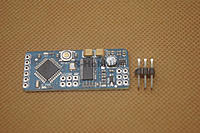
It is already integrated with Arduino Atmega328p & MAX7456 (another chip that will overlay data like the LM1881 chip) and it can be bought for £10 here

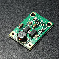
To use this board with the V929, one must increase the voltage from the 1s 3.7v lipo to 5v. To do this we could use a £1 5v booster like this: 
Name: 3333332.JPG
Views: 5
Size: 95.5 KB
Description:

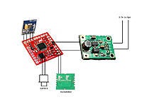
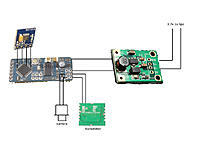
Then, we could solder the BMP180 to the minimOSD and make an osd like this:
Name: OSD-diag1.jpg
Views: 18
Size: 125.0 KB
Description:

Cost should be around £13 (minimosd = £10, booster = £1, BMP180 =£2)
Weight should be around 8g

It is an option...